


 The Peripheral Control project from Demand Peripherals makes it
easy to build a Linux based robot or other automation. Our
key differences are a Linux API and the 100 percent code reuse
that seems inherent with FPGA based peripherals. No more
having to write all of the software layers from the hardware
up to your application.
The Peripheral Control project from Demand Peripherals makes it
easy to build a Linux based robot or other automation. Our
key differences are a Linux API and the 100 percent code reuse
that seems inherent with FPGA based peripherals. No more
having to write all of the software layers from the hardware
up to your application.
The API is ASCII commands over a TCP connection. This means
you can write your Linux application in almost any programming
language: C, C++, Java, Perl, PHP, or Python. We even have
BASH wrappers around the commands so you can program or test
your automation from the command line!
The video to the right is a nice introduction to FPGA-based
controllers and to the simple API we offer. After watching
the video you will have a full understanding of what it does,
how it works, and how to use it in your application.
Changing peripherals is easy. Just go to the support page Build Your FPGA Image, select your new peripheral set, tell us where to email the FPGA image and press Submit. The email address associated with your purchase of the FPGA card gives you access to the backend service that builds FPGA images. There is no limit on how many FPGA images you can request.
 Demand Peripherals can dramatically improve your time-to-market
for new robots or other automation since there is no MCU
code to write and interface card schematics are open-source.
Demand Peripherals can dramatically improve your time-to-market
for new robots or other automation since there is no MCU
code to write and interface card schematics are open-source.
The design cycle for building a microcontroller based robot
is eight to twelve months just to get to the point that you
can start writing the high-level Linux application. The
problem is that you usually have to start from scratch for
the circuit design and all of the MCU code.
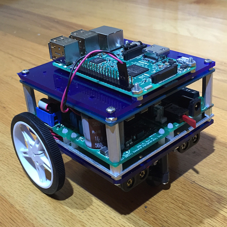
 A typical workflow when using Peripheral Control is to build
a prototype using off-the-shelf cards. This prototype
will be API complete and ready for use by the high level
application programmers. Once the application is underway
on the prototype hardware you can have your electrical engineers
collect the schematics and arrange them on one board
and start the board layout and fabrication. The advantage
in this approach is there is no MCU firmware to write
and you can have an API complete prototype in a week.
A typical workflow when using Peripheral Control is to build
a prototype using off-the-shelf cards. This prototype
will be API complete and ready for use by the high level
application programmers. Once the application is underway
on the prototype hardware you can have your electrical engineers
collect the schematics and arrange them on one board
and start the board layout and fabrication. The advantage
in this approach is there is no MCU firmware to write
and you can have an API complete prototype in a week.
The Peripheral Control FPGA code is free for non-commercial use.
The daemon is released under the GPLv3 and the schematics are
released under a Creative Commons license. To use the system
commercially requires a purchased license. the license costs
seventy-five
hundred dollars and includes the following:
- Ability to distribute the FPGA image
- Non Creative Commons use of the schematics
- Non GPL use of the pcdaemon source code
- License for the patented circuit of the ESPI
- Five hours of telephone support
Need help with the schematic capture and board layout? Let us know. Demand Peripherals can help build your prototypes.
A detailed description of the system operation and architecture can be found here.
A list of the peripherals and their descriptions can be found here.
A list of interface cards can be found here.
A complete description of the API can be found here.
You can specify and build a custom FPGA image with your selection of peripherals here.