


The EI2C peripheral and card provide a general purpose I2C interface for your robot or other automation.
Reads and writes to the I2C bus are organized as packets that can have up to 13 data bytes. You can intermix reads and writes but each transition from read to write (or back) takes one byte from the 14 data bytes available.
Read responses are available from a separate resource and each read response indicates success or failure of the packet.
Hardware:
The I2C interface card supports clock-stretching and has clock rates of 400 and 100 KHz. The card must be the only master on the bus.
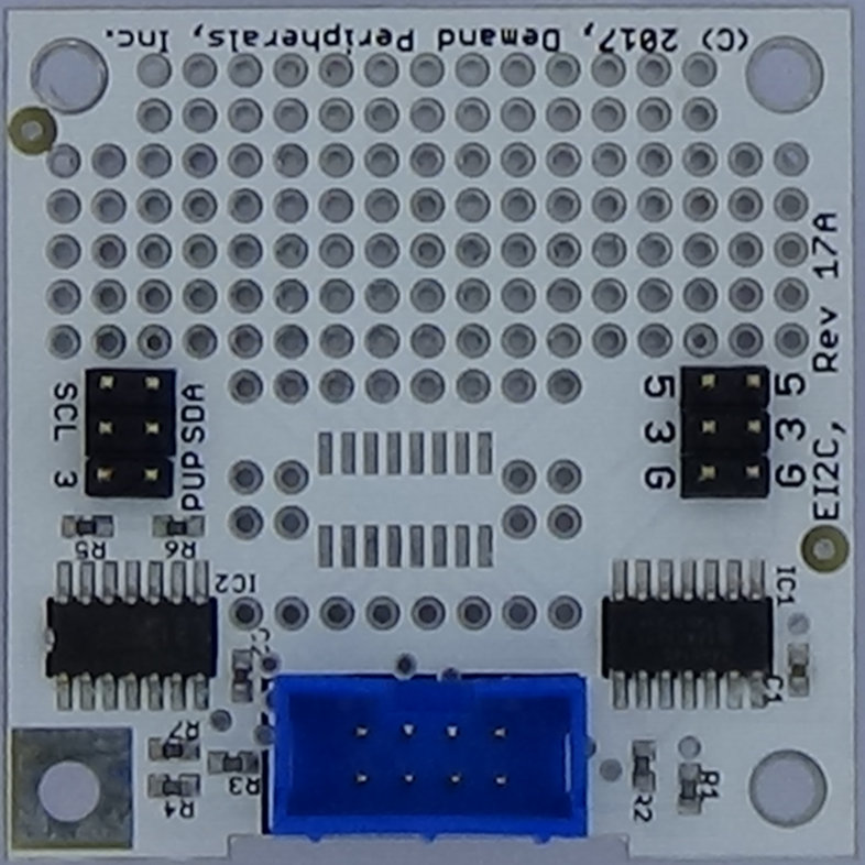
The EI2C card has a prototyping area as well as connectors for SCL, SDA, +3.3, +5, and ground. Jumpers let you select the pull-up resistor voltage and let you use external pull-up resistors if you wish. More information about the EI2C card is available here: /cards/ei2c.html
Resources:
Resources for the EI2C peripheral include clock rate configuration and resources to send and receive packetsconfig : The clock rate in Kilohertz as a single integer terminated by a newline. Valid clock rates are 400 and 100.
data : the data to send to the I2C device as up to 13 values separated by spaces and terminated by a newline. Data bytes are given in hexadecimal and an 'R' marks the transition from write to read in the packet. The format for an I2C packet is:
<addr> <hex|R> ... <hex|R>
The pcget command provides both read and write functionality for the EI2C peripheral. Additional bytes on the pcget command line are sent to the I2C device and each byte sent gives another hex value in the response.
Responses start with either an 'A' or an 'N' to indicate whether all bytes were ACK'ed. The second string in the response is the hex value of the address. The remaining hex values are the read responses or an echo of the data written. The 'w' and 'r' characters indicate a write or read response. A newline terminates the response.
Examples:
The Microchip MCP23008 is an 8 bit expansion port with an I2C interface. The part has ten internal read-write registers for configuration and data. Commands to the part have the I2C address, a write of the register number, and a read or write of the data for that register. The command to write a 55 to register 3 in the MCP23008 with an address of 0x20 would be:
pcget ei2c data 20 03 55
The response to the above read command would be:
A 20 w 03 55
A read of that same register would be:
pcget ei2c data 20 03 R
The response to this command would be:
A 20 w 03 r 55