


The ESPI peripheral and card provide a general purpose SPI interface for your robot or other automation. Reads and writes to the SPI bus are organized as packets that can have up to 14 bytes.
Hardware:
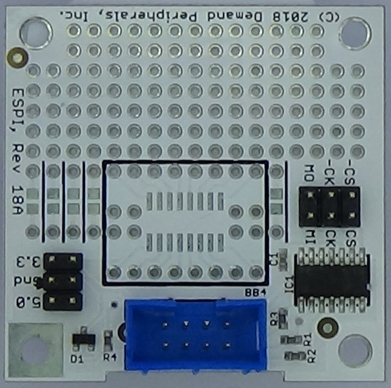
The ESPI, "encoded clock SPI", peripheral supports SPI Modes 0 2. It does not support SPI modes 1 or 3. Data is sent as a packet with up to 14 bytes. Four different SCK clock frequencies are supported. You can configure the chip select line to be forced high, force low, active high during transfers or active low during transfers. More information about the ESPI card is available here: /cards/espi.html
Resources:
Resources for the ESPI peripheral let you set the clock frequency and the polarity of the chip select.config : the clock rate and chip select mode as as two strings separated by space and terminated by a new line.
The sck clock frequency can be one of four values. Invalid values are rounded to the nearest valid value. Available clock frequencies are:
   2000000 -- 2 MHz
   1000000 -- 1 MHz
    500000 -- 500 KHz
    100000 -- 100 KHz
The behavior of the chip select line is specified as a two character strint. The following are the possible choices:
  'al'  -- active low: low during transfers, high otherwise
  'ah'  -- active high: high during transfers, low otherwise
  'fl'  -- forced low
  'fh'  -- forced high
A sample configuration line for a SPI port using SPI Mode 0 at 1 MHz, and with an active low chip select could be entered as follows:
pcset espi config 1000000 al
data : the data to send to the SPI device as up to 14 hex values separated by spaces and terminated by a newline.
The pcget command provides both read and write functionality for the ESPI peripheral. Additional bytes on the pcget command line are sent to the SPI device and each byte sent gives another hex value in the response.
For example:
    pcget espi data 03 12 34 00

Might return:
    00 67 89 ab