


The PWMIN4 peripheral lets you measure the duty cycle of four inputs. Outputs include the duty cycle as a decimal fraction as well as an output that gives the relative timing of the pulses.
Hardware:
The quad PWM input peripheral measures the widths of periodic pulses on each of the four pins on a Baseboard connector. Pulse widths are measured with 16 bits of accuracy for both the high and low periods of a pulse. The clock source driving the pulse width counters ranges from 5 Hertz to 20 Megahertz.
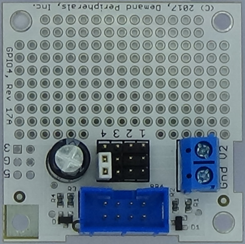
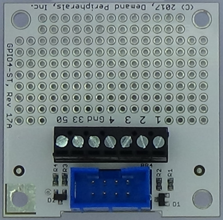
The PWMIN4 peripheral uses direct input from FPGA pins. That is, the peripheral works best with either of the GPIO cards. More information about the GPIO cards is available here cards/gpio4.html and here cards/gpio4-st.html.
Resources:
PWMIN4 has resources to set the sample clock rate, and to report the pulse low and high times.clock_rate : frequency of the PWM sample counters. A clock frequency of zero turns off the peripheral. The frequency is given in Hertz and must be one of the following:
            20000000
            10000000
             5000000
             1000000
              500000
              100000
               50000
               10000
                5000
                1000
                 500
                 100
                  50
                   0
counts : duty cycles of the four inputs. Dutycycle is a read-only resource that gives the number of clock cycles for the low and high times of each input. A zero indicates that a timeout occurred before the completion of the cycle for that input. Dutycycle works with pccat.
The peripheral captures three transitions for each of the four input lines. Only three transitions on a pin are needed to determine the low and high clock counts (and the thus the frequency and duty cycle) for that input. Input from a pin is ignored once all three transitions on it have been recorded. This input masking prevents a fast changing input from overflowing the sample buffer.
The format of the output on the counts resource is:
Examples:
Many radio controlled airplanes use four servos as actuators. Configure the PWMIN4 peripheral to monitor and output the pulse widths from a four channel RC receiver.
The cycle time on an RC receiver is usually 20 milliseconds. A clock rate of 1 MHz gives maximum cycle time of 65 milliseconds. (5 MHz is too fast, giving a maximum cycle time of just over 13 milliseconds.) Since the on time for an RC control pulse is between one and two milliseconds, a time resolution of 1 microsecond corresponds to about 10 bits of precision.
Configure the clock and start the stream of duty cycle readings
    pcset pwmin4 clock_rate 1000000
    pccat pwmin4 counts